150 Case Part 2 – Building a Giant
By Kory Anderson
We have achieved some major milestones in the first four months of 2018 to keep on track for our debut deadline on September 7, 2018. We have cast a great majority of the parts at the foundry and I’ve been making runs every few weeks to Gary Bradley’s in Sheridan, WY to keep up with machining.
We finished machining the engine frame in Webster, SD which was a huge challenge due to the size of the casting (nearly 1,000 lbs.) and the extreme accuracy that we need to hold in the tolerances. Once we had the engine frame and bearing housings machined we installed them into the fixture that I had built to assemble the engine and pour the babbitt bearings. Gary was busy pouring the babbitt bearings while I continued to machine parts for the engine assembly. Once the bearings were all babbitted, we then line bored them all to size giving each of them a clearance of .006” for the 4-5/8” crankshaft.
We took great care in getting everything to line up perfect. The reason we built a fixture for doing this was because on the original Road Locomotives they didn’t have the crankshaft and low speed shaft perfectly parallel, which caused the babbitt to melt out due to the extreme force on the bearings. We then line bored the cross head slide in the engine frame using some jigs that we made to ensure it was perfectly perpendicular to the crankshaft and in line with the center of the shaft.
After the engine frame and all the bearings were line bored, we were ready to assemble the engine. We assembled the crankshaft first with the eccentric strap, governor pulley, sliding power steering gear, and first low speed gear. Then we assembled the low speed shaft with the intermediate power steering gear and low speed reduction gears. After fabricating the clutch arm from steel and installing bronze bushings, we assembled the clutch mechanism and pressed on the crankshaft gear. Finally, we assembled the clutch arm onto the crankshaft completing the assembly of the main engine drive components.
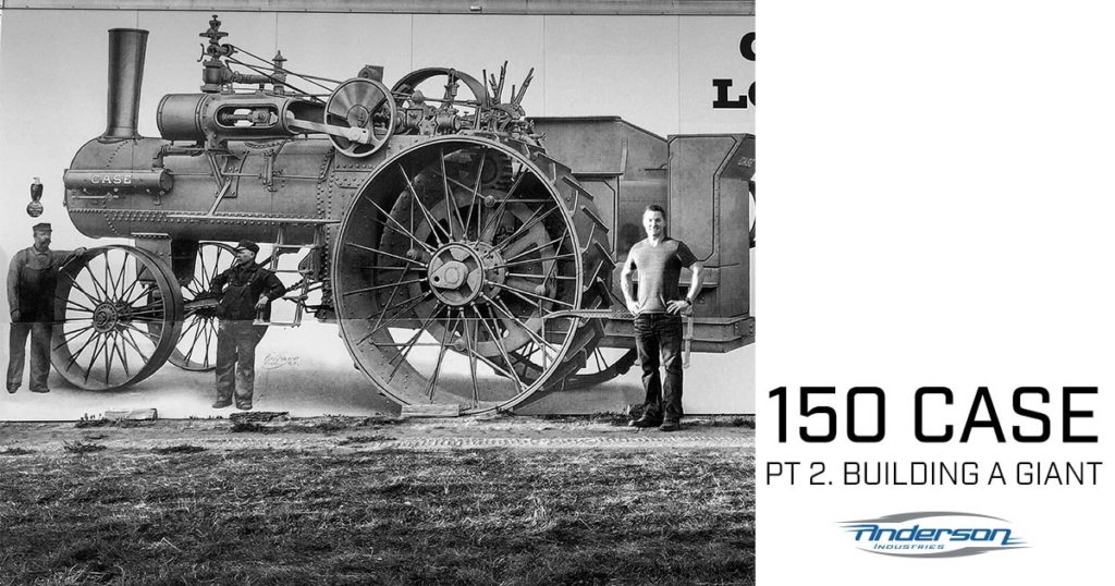
Meanwhile in Fargo, ND at Larson Welding, Jim Briden and I had been planning for about 6 weeks how we would build the massive rear wheels. Each wheel is 8 feet in diameter and weighs over 3 ton. Jim modified a hydraulic squeezer that we could use to punch the inside angle and channel irons in the wheels. Once I had all the steel parts fabricated and lugs, hubs, and bull gears machined - the real work began. We rounded up an incredible crew of friends who helped us over the course of a few weeks to assemble and build the rear wheels. We installed over 1,200 hot ¾” rivets! Most of them we were able to squeeze with the large hydraulic squeezer I had designed and was welded together by Wimpy Anderson in Jim’s shop. Around 80 rivets had to be put in by hand with the air hammer when we got to riveting in the drag links because we didn’t have any more room to get the squeezer in. By the time we were done, we really had the building of wheels down to a science. We built each wheel in just under 3 days which was much less than we had planned. After the wheels are powder coated they will travel to Sheridan to join the rest of the engine coming together.
At the end of April we will have the rear wheels built and main engine components assembled onto the fixture. The next step will be to raise the engine assembly onto the boiler to drill and locate all the mounting brackets. We will then leave the engine on the boiler and begin assembling the intermediate gear, differential gear, and cannon bearings. With only 3 months until our targeted test firing of the engine I better stop writing and get back to work! We are really looking forward to seeing everyone this fall at the James Valley Threshing show. And a tremendous thanks to all the friends who have been helping us along the way.


